DOE mittels FSL
Nachfolgende Skripte veranschaulichen, wie die FSL unmittelbar zur Automatisierung von Berechnungen am Beispiel einer kombinatorischen Variation von Geometrieparametern, d. h. einer einfachen Form des Design of Experiments (DOE) genutzt werden kann.
Das DOE bezieht sich auf die nachfolgend gezeigte einfache Maschinentopologie.
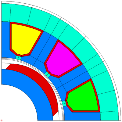
Veränderliche sind die Nutzschlitzbreite, die Polbedeckung und der Polradius. Zielgrößen sind das Nutrastmoment, das Lastmoment (Drehmomentmittelwert) und das Lastpulsationsmoment.
Skript 1 - DOE und Ausgabe der Zielgrößen
Das Skript gibt die Werte der Designvariablen vor, stößt die Modellerstellung sowie Berechnung an und gibt die Ergebnisse in Bezug zu den Vorgaben in einer Datei aus.
--------------------------------------------------------------------------------
-- Common Definitions ----------------------------------------------------------
--------------------------------------------------------------------------------

exit_on_error = true
exit_on_end = true
verbosity = 2

--------------------------------------------------------------------------------
-- Simple full factorial DOE ---------------------------------------------------
--------------------------------------------------------------------------------

-- This example shows how to use FSL to perform a simple DOE
-- directly within FEMAG.
-- FEMAG should be started with the parameter "-b" to suppress
-- the mask and graphic window (they may steal the focus).

var1_start = 3    -- start of first range
var1_end = 8      -- end of first range
N1 = 2            -- number of steps (5)

var2_start = 60   -- start of second range
var2_end = 80     -- end of second range
N2 = 2            -- number of steps (5)

var3_start = 20   -- start of third range
var3_end = 33.5   -- end of third range
N3 = 2            -- number of steps (5)

fout = assert(io.open("results.txt","w"))
fout:write("# Full factorial DOE using the FEMAG Script Language\n");
fout:write("#\n");
fout:write("# i          var1           var2         var3     T cogging        T harm        T load\n");
fout:write("#            [mm]           [%]          [mm]          [Nm]          [Nm]          [Nm]\n#\n");

i=1
for i1=1,N1 do    -- loop over all combinations
  for i2=1,N2 do
    for i3=1,N3 do
      var1 = var1_start+(var1_end-var1_start)*(i1-1)/(N1-1)   -- calculate new values
      var2 = var2_start+(var2_end-var2_start)*(i2-1)/(N2-1)
      var3 = var3_start+(var3_end-var3_start)*(i3-1)/(N3-1)

      dofile("exampleDOE_1.fsl")  -- execute FE model generation and evaluation
                                  -- (good to do this in a separate file)

      fout:write(string.format("%03d  %12g  %12g  %12g  %12g  %12g  %12g\n",
                  i,var1,var2,var3,T[2],T[3],T[1]));
      fout:flush()

      -- This cleanup code only works on Linux
      os.execute("rm *.AUX7-*")     -- garbage collection (if necessary)
      os.execute("rm *.ISA7-*")
      i = i+1                       -- increase the overall number of variants
    end
  end
end

io.close(fout)    -- do not forget to close the output files
Skript 2 - Modellerstellung und Simulation
Das Skript erstellt das FE-Modell unter Nutzung der in FEMAG vorhandenne parameterbasierten Maschinenmodelle und führt eine Leerlauf und Lastrechnung durch.
--------------------------------------------------------------------------------
-- Common Definitions ----------------------------------------------------------
--------------------------------------------------------------------------------

exit_on_error = true
exit_on_end = true
verbosity = 2

--------------------------------------------------------------------------------
-- Modell Generation -----------------------------------------------------------
--------------------------------------------------------------------------------

new_model_force("exampleDOE","Simple DOE using FSL")

global_unit('mm')   -- Global unit (m, cm, mm)
pickdist(0.001)     -- Snap distance

cosys('polar')

-- Define FE Control Data

m.hc_min          =       95.0      -- Limit demagnetisa > 0:[%]Hc,<0:[kA/m]
m.con_hdcopy      =       0.00      -- Hc-copy:Name:auto:0,intact:1, none:-1
m.b_max           =       2.40      -- Max Induction [T] in colorgradation
m.b_min           =       0.00      -- Move inside: 0 , Move outside: > 0
m.calc_fe_loss    =       0.00      -- Calcul. FE-Loss > 0, areas <0, no = 0
m.eval_force      =       0.00      -- Eval. force density > 0, no <= 0
m.allow_draw      =       1.00      -- Draw Graphics :> 0: yes, 0:  no
m.fline_dens      =       1.00      -- F-Lines: 1: small, 2: medium, 3:thick
m.num_flines      =      10.00      -- Number of Field-lines:      < 100 > 2
m.name_bch_log    =       0.00      -- Name bch-file in Logfile:> 0:yes,0:no
m.st_size_move    =       0.00      -- Step size move: r/ph:[degr], x/y:[mm]
m.num_nonl_it     =       1.00      -- Number of nonlinear Iterations   < 99
m.perm_mode       =       0.00      -- Permeability mode:>0:restore,0:actual
m.error_perm      =      0.500E-01  -- Rel. Permeability error < 0.1     [%]
m.allow_demagn    =       0.00      -- Allow Demagnetisation:= 1:yes,= 0:no
m.maenergy        =       0.00      -- Force from magn energy 1 :yes,= 0:no
m.el_order_ag     =       1.00      -- El. order in air gap: lin=1: quadr=2
m.export_scrpt    =       0.00      -- Export parameters in script: yes > 0

pre_models("FE-contr-data");

-- Define the Basic Model Parameter

m.tot_num_slot    =         12      -- Numer of Slots
m.num_slots       =       3.00      -- Number of slots in Model (Rot-Mot)
m.num_poles       =          4      -- Number of Poles 2p            (>= 2)
m.npols_gen       =          1      -- Number of Poles simulated     (>= 1)
m.arm_length      =         50      -- Effect. armature length          [mm]
m.fc_radius       =       34.2      -- Radius air-gap center (torque)   [mm]

pre_models("basic_modpar");

-- Generate Stator

m.yoke_diam       =       130.      -- Outer diameter yoke   DAS        [mm]
m.inside_diam     =       70.0      -- Inner diameter        DIS        [mm]
m.slot_height     =       20.0      -- Total slot height     HSL        [mm]
m.slot_h1         =       2.00      -- Slot opening height   H1S        [mm]
m.slot_h2         =       4.00      -- Slot head height      H2S        [mm]
--m.slot_width      =       3.00      -- Slot width SWI,< 0 groove in Slot[mm]
--m.slot_width      =       8.00      -- Slot width SWI,< 0 groove in Slot[mm]
m.slot_width      =       var1      -- Slot width SWI,< 0 groove in Slot[mm]
m.slot_r1         =       0.00      -- Upper Radius          R1S        [mm]
m.slot_r2         =       0.00      -- Lower Radius          R2S        [mm]
m.wedge_width1    =       0.00      -- Distance middlepoints B1S        [mm]
m.wedge_width2    =       0.00      -- Distance middlepoints B2S        [mm]
m.nodedist        =       1.00      -- Rel. node distance in iron > 0.5
m.middle_line     =       0.00      -- Layers: 0,vert:1,horiz:2,vert+horiz:3
m.tooth_width     =       9.00      -- Tooth width TW (replaces B1, B2) [mm]
m.slot_top_sh     =       0.00      -- Top of slot: corner=2, line=1, arc=0
m.airgap          =       1.00      -- Mesh in airgap: 2/3 airgap height[mm]
m.tot_num_sl      =         12      --  Total number of teeth on 2pi
m.num_sl_gen      =          3      --  Number of teeth be generated
m.zeroangl        =       0.00      -- Reference angle to x-axis [grad]
m.mcvkey_yoke     =    'dummy'

pre_models("STATOR_3");

-- Generate Magnet Sector Rotor

m.magn_rad        =       33.5      -- Radius Magnet airgap side    RA  [mm]
m.yoke_rad        =       20.0      -- Radius iron yoke inside      RI  [mm]
m.magn_height     =       5.00      -- Magnet height                HM  [mm]
m.magn_width      =       var2      -- Magnet width: > 0: [%], < 0: BM  [mm]
m.airgap          =       1.00      -- Mesh height (2/3 airgap)         [mm]
m.nodedist        =       1.00      -- Rel. Node distance > 0.2    ..
m.condshaft_r     =       20.0      -- Conduct. Shaft Radius:< yoke_rad [mm]
m.magn_num        =       1.00      -- Number Magnet sections:   > = 1
m.magn_perm       =       1.05      -- Radius Iron between magnets      [mm]
m.magn_l          =       100.      -- Magnet Length: < 150 %            [%]
m.magn_ori        =       1.00      -- Magnet: par = 1, Pol = 2, halbach = 3
m.magn_type       =       2.00      -- Mag Type:Ac:1,Acp:2,Rc:3, Rcp:4,AAp:5
m.magn_shape      =       var3      -- Magnet surface radius or shape HA[mm]
m.br_height       =       0.00      -- Iron bridge height: = 0: none  BH[mm]
m.br_width        =       0.00      -- Iron bridge width : = 0: none  BW[mm]
m.zeroangl        =       0.00      -- Reference angle to x-axis [grad]
m.cond_shaft      =       0.00      -- El. Conductivity of shaft [S/m]
m.mcvkey_yoke     =    'dummy'
m.mcvkey_mshaft   =    'dummy'

pre_models("Magnet-Sector");

-- Specify Magnet Properties

m.remanenc        =       1.20      -- Remanence  Br  (Ref:20 Degree C)  [T]
m.relperm         =       1.05      -- Rel. Permeability muer
m.spmaweight      =       7.60      -- Specific Weight Magnets       [gr/cm3]
m.temcoefbr       =     -0.100      -- Temperature Coefficient for Br   [%/K]
m.temcoefhc       =     -0.100      -- Temperature Coefficient for Hc   [%/K]
m.magntemp        =       20.0      -- Magnet Temperature          [Degree C]
m.magncond        =      0.625E+06  -- Magnet el. conductivity      [1/Ohm m]
m.magsegwid       =        nil      -- Magnet segment width              [mm]
m.magseglen       =        nil      -- Magnet segment length z-direction [mm]

pre_models("Magnet-data");

-- Connect Stator to Rotor and Apply Boundary Conditions

pre_models("connect_models");

-- Generate Winding

m.num_phases      =       3.00      -- Number of Phases m  <= 500
m.num_layers      =       1.00      -- Number of Layers (slot sides)per slot
m.num_wires       =       20.0      -- Number of wires per slot side
m.current         =       1.00      -- Wdg-Current [A] or flux [Vs/mm],peak
m.coil_span       =       3.00      -- Coil span Y  >= 1
m.num_slots       =       3.00      -- Number of slots in Model (Rot-Mot)
m.mat_type        =       1.00      -- Ma-type:1=Rot;21=lin-x;22=lin-y
m.wind_type       =       1.00      -- W-typ:1=w&cur;2=w&flux;3=bar&cur
m.win_asym        =       1.00      -- asy. slot pitch: 1=sym.; <1=asym.
m.wdg_location    =       1.00      -- Windg location:1: stator, 2: rotor
m.curr_inp        =       0.00      -- Curent:Const:0, Q-axis:1, D-axis:-1
m.dq_offset       =       0.00      -- Offset to D-axis:>=0 Compl;<0 only Re
m.xcoil_1         =     44.433      -- center coordinate of 1. coil side [mm]
m.ycoil_1         =     11.906      -- center coordinate of 1. coil side [mm]
m.xcoil_2         =      0.000      -- center coordinate of 2. coil side [mm]
m.ycoil_2         =      0.000      -- center coordinate of 2. coil side [mm]

pre_models("Gen_winding");
pre_models("gen_pocfile");

--------------------------------------------------------------------------------
-- Machine Simulation ----------------------------------------------------------
--------------------------------------------------------------------------------

-- PM/Reluctance Motor Simulation (open circuit and load)

m.move_action     =       0.000       -- Move Action: rotate=0, linear=1
m.num_pol_pair    = m.num_poles/2     -- Number of Pole pairs           (>= 1)
m.speed           =    5000.000       -- Speed: rotate                 [1/min]
m.skew_angle      =       0.000       -- Skew angle                  [Deg, mm]
m.nu_skew_steps   =       0.000       -- No of skew sect:>0:finite,0:infinite
m.eval_force      =       0.000       -- Evaluate force density: no = 0,yes >0
m.current         =      40.000       -- Nominal stator coil current(Peak) [A]
m.angl_i_up       =       0.000       -- Angle current I vs. voltage Up  [Deg]
m.num_par_wdgs    =       0.000       -- Number of parallel Windings   (>= 1)
m.magn_temp       =      20.000       -- Temperature Magnet            [Deg C]
m.optim_i_up      =       0.000       -- Optimize < I vs Up : no = 0, yes > 0
m.calc_fe_loss    =       0.000       -- Calculate Losses:>0, areas>0, no = 0
m.nu_move_steps   =          31       -- Number of move steps
m.range_phi       =       180.0       -- Move range angle
m.phi_start       =       0.000       -- Start angle
m.pm_eff_aktiv    =         100       -- Effektive Magnetlaenge [%]
m.fc_mult_move_type =        0.       -- Type of move path in air gap
m.pocfilename     = 'example15_4p.poc' --    POC file

run_models("pm_sym_fast");

post_models("r_torque","T")   -- Return results in Variable "T"
                              -- T[1] load torque
                              -- T[2] cogging torque
                              -- T[3] harmonic torque
save_model('close')
Ausgabedatei
Beispiel für die entstehende Ausgabedatei mit den Veränderlichen und den Zielgrößen.
# Full factorial DOE using the FEMAG Script Language
#
# i          var1           var2         var3     T cogging        T harm        T load
#            [mm]           [%]          [mm]          [Nm]          [Nm]          [Nm]
#
001             3            60            20     0.0128383      0.186146       5.96762
002             3            60        23.375      0.107266      0.466766       6.40093
003             3            60         26.75      0.208328      0.712521        6.7077
004             3            60        30.125       0.30471      0.923281       6.94103
005             3            60          33.5      0.398507         1.102        7.1263
006             3            65            20     0.0212331      0.094842       6.06792
007             3            65        23.375     0.0481472      0.273508       6.59734
008             3            65         26.75     0.0959057       0.44236        6.9691
009             3            65        30.125      0.115449      0.591475       7.24707
010             3            65          33.5      0.105495      0.726272       7.46296
011             3            70            20     0.0263271     0.0562837        6.1102
012             3            70        23.375    0.00604528       0.12144       6.73694
013             3            70         26.75    0.00935386      0.189668       7.17874
014             3            70        30.125    0.00572925      0.247008       7.51182
015             3            70          33.5     0.0338019      0.301635        7.7703
016             3            75            20    0.00959954     0.0412285       6.46365
017             3            75        23.375     0.0120574     0.0335329       6.82524
018             3            75         26.75     0.0635402     0.0477435       7.33499
019             3            75        30.125      0.141136      0.107096       7.71997
020             3            75          33.5       0.20935      0.173654       8.02675
021             3            80            20    0.00526817     0.0126245       6.70181
022             3            80        23.375    0.00811732     0.0104316       6.86939
023             3            80         26.75     0.0751196      0.104514        7.4444
...
Veranschaulichung der Zielgrößenwerte
Darstellung zweier Zielgrößen und der sich im linken unteren Bereich ergebenden Grenzkurve, die als eine erste Näherung der Pareto-Front angesehen werden kann.
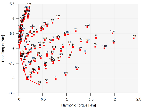
Es existieren Designs, wie z. B. die mit den Nummern 18, 19 und 22, die eine deutliche Reduzierung der Drehmomentschwankung in Aussicht stellen bei noch verhältnismäßig großem Lastmoment (Drehmomentmittelwert) der Maschine. Die Abbildung zu Beginn dieses Abschnittes zeigt das Design 18, das in diesem einfachen Fall erwartungsgemäß eine kleine Nutschlitzbreite, einen mittleren Polradius sowie eine relative Polbedeckung von nahe 80% aufweist.